Rambling thoughts on gyuto profiles

Kitchen Knife Forums

Help Support Kitchen Knife Forums:

This site may earn a commission from merchant affiliate links, including eBay, Amazon, and others.
Absolutely. The length of the yellow lines determines the amount of curve in my style of doing things. With a bit of practice I can use it to recreate any profile, but I guess the problem is it might not be all that intuitive.
6RcGQtq.png
 
It was mentioned before that the height of your cutting board is important when considering the spine/handle angle (or flat-spot angle, the two being different sides of the same coin).
iqLed5G.png

I find that (a) tends to be easier to use on a higher surface, while (b) is easier to use on a lower surface. Many of the pro chefs here would understand what it's like when someone is using your favorite spot in the kitchen and you have to go and find another bench to work on. I tend to use different knives depending on the height of the bench I'm working with.

To add to this, the profile shape will often influence the way I want to move my arm and wrist, depending on what I'm cutting of course.
On a higher table (a) will have more of a chopping wrist action with the lower arm moving up and down, pivoting at the elbow in a movement similar to a drummer. 240mm Shigs are amazing for this, and I'm sure many others are too.
On a lower table (b) tends towards a locked wrist push cut, and relies more on forward-and-down arm movements. Lifting the knife off the board is optional. This is my default style for most work, and so I personally like my knives to have more of a spine angle and prefer to work on lower tables.
CeF763s.png

Sori/re-curve spines are basically a mix of the two.

When I'm by the grinder, I typically roll the edge on a flat surface, that will typically tell me if I need adjustments my eye did'nt catch, works like a charm every time, repeatable and for every different size/model o_O
I have a scrap cutting board next to my grinder for the same reason :D
 
Last edited:
There is to my knowledge no established mathematical method that can be applied to describing a curve that gives different weights to different tangent lines. You either know the angle at a point and can thus construct a tangent line and use that as a requirement for a curve equation or you don't. Nonetheless tangent at tip can be used as a boundary condition just like any other. May well turn out to be more successfull than the four I suggested but would have to check a few profiles to see.
 
Well in the past I've asked people to send me a video of them working so I can tailor the knife to their needs, but it seems like maybe I'm asking too much. The easier option is just to ask for someone's favourite knife profile in a picture, and I can extrapolate plenty of information from it.
 
I should also mention that over many years of sharpening, blade (a) will gradually turn into (b) unless you make a conscious effort not to let it happen.

As I use my main knives over the years they start to feel flatter in the belly and more angled at the handle/spine - which in turn improves the feel and feedback as it slowly reaches my sweet spot.
Then one day it's suddenly too much, the knife handles like crap and needs re-profiling.

My Sukenari 240mm ZDP has reached the point of its life where it's gone over the sweet-spot for me and needs re-profiling.
As new profile:
IMG_7397_600x.jpg
iqLed5G.png
4EHCQsj.jpg
My old faithful. She needs some loving. :rolleyes:
 
Last edited:
As I mentioned earlier, here is one of my old workmates knives sharpened by some idiot going around with a grinder, charging money for sharpening.
It's the worst job I've ever seen without a shadow of a doubt. Of the twenty knives he worked on, ten of them are complete garbage now.

I'm still not sure how I'm going to salvage these... I mean, look at the knuckle clearance!
gps88lD.jpg


The important point is - flat spot should never be completely flat and there should be a tiny upcurve towards the heel.
Heh, not on these knives! :D
 
Last edited:
As I mentioned earlier, here is one of my old workmates knives sharpened by some idiot going around with a grinder, charging money for sharpening.
It's the worst job I've ever seen without a shadow of a doubt. Of the twenty knives he worked on, ten of them are complete garbage now.

I'm still not sure how I'm going to salvage these... I mean, look at the knuckle clearance!

Make it a gyutohiki?

Would it even be worth the investment in belts?
 
As I mentioned earlier, here is one of my old workmates knives sharpened by some idiot going around with a grinder, charging money for sharpening.
It's the worst job I've ever seen without a shadow of a doubt. Of the twenty knives he worked on, ten of them are complete garbage now.

I'm still not sure how I'm going to salvage these... I mean, look at the knuckle clearance!
gps88lD.jpg


Heh, not on these knives! :D

That looks aweful! The guy should pay the vaule of those knives back.
 
Holy... that's a lot of reading I just did. But you guys put lots of things in perspective. I agree that for me at home (not a pro) that the height of the food prep, board height, and my height does affect which knife is more comfortable to use. However in 99% of the time for home cooks.. I think we adapt to whatever is available (and complain that a knife is dull), more so then which knife profile is perfect.

I think there is one I would agree I like more but I seem to be able to quickly adjust to whatever I have on hand. Obviously not going through 2o+ lbs of food though.
 
What you're doing here is very interesting. From a math/geometry/CAD standpoint, I think there are a couple things worth considering.

First, about nature of the curve/spline things you're using. They're known as Bezier curves - specifically, cubic Bezier curves. One nice thing is that they can be differentiated. This is useful because the second derivative of position is curvature (conveniently the inverse radius of curvature, ie curvature value of 0.1 equals a radius of 10mm).
Another characteristic - and you alluded to this earlier, but it’s somewhat relevant to this post - is that by definition, the curve arrives at the endpoints from the direction of the control points. This means that tip angle is equal to the angle from the tip control point to the tip point. As a result, placing that control point directly below the tip radiuses the tip.
It's also not difficult to calculate the belly similar to the method used by Merlin & HRC.

I've created a spreadsheet that takes the control point coordinates and generates the edge, the slope/angle along the edge, and the curvature along the edge. Each of those is plotted. It also calculates the belly point.
I think it also has potential use as a design generation/validation aid.
Also, I liked the idea mentioned earlier of some sort of knife profile database. By quantifying edge shape, you can filter and search more easily. For instance, if a maximum curvature or deviation from flat was defined, you could search for flat spot length.

Here's the spreadsheet - feel free to make a copy if you like, or I'm happy to add you as an editor if you're interested.
Edge Curve Analysis Spreadsheet
 
Cubic Bezier curves, aye? Thanks for giving me the name, I wasn't aware.
Here's the spreadsheet - feel free to make a copy if you like, or I'm happy to add you as an editor if you're interested.
Edge Curve Analysis Spreadsheet
Holy crap - This thing is awesome!
Did you have the spreadsheet before this thread, or was it something you created from my ramblings? It perfectly fits my way of thinking of profiles! :eek:

I'm going to try and get my hands on a popular knife shape, an angle cube and a ruler to see how accurate a representation I can get using your spreadsheet and the measurements between the basic points.
 
Last edited:
For those of you with fried brains :D, this is how it works.
After filling in the seven boxes highlighted in red, the spreadsheet takes the coordinates of three points and - with the heel as a reference - uses them to calculate the flat spot and the belly curve, as well as some other information in the output.
EYGry7s.png
If you resize the Edge Shape graph 1:1 with a ruler on your screen, you'll get the edge profile in its real shape and size on your screen.
Edge Slope represents the measurement a protractor would give you at any given point along the edge.
Edge Curvature shows the strength of the curve, which exponentially increases as it travels towards the tip.
Uhlvs2L.png

This would be an awesome way to start a knife profile database. It's not perfect though, as the control points (P1, P2) can be difficult to find on a knife. The rest is easy though.
 
Last edited:
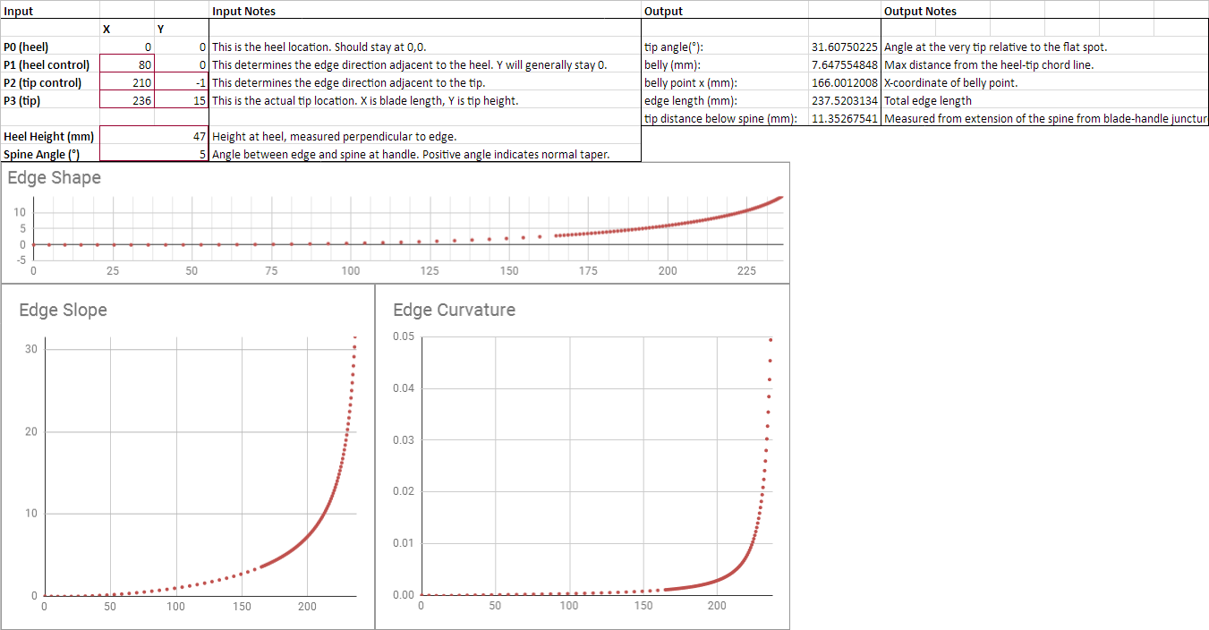
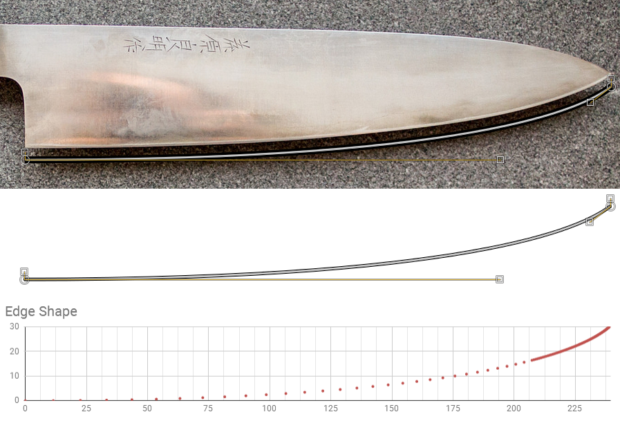
I'm glad you liked the spreadsheet. I put it together after I came across this thread. If you check the column labeled "R", that's the equivalent radius of curvature at each point.

My hope would be to (eventually) create a simple enough interface that it's approachable to anyone with an interest, and make the math(s) part somewhat optional.

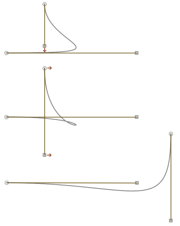
Finding the control point locations doesn't have to be too difficult, as long as you're comfortable making the curve match the edge. There are two fairly simple ways to get their locations.

The first is to create your curve in 2D CAD - Draftsight is a freeoption from Dassault. You could use NanoCAD or Creo Sketch, or even AutoCAD if you've got it. You'll insert the image, put the heel at (0,0), draw the curve, then scale to get the right length. Then, you can select the spline and look at the coordinates of each control point:
upload_2018-10-11_10-51-59.png

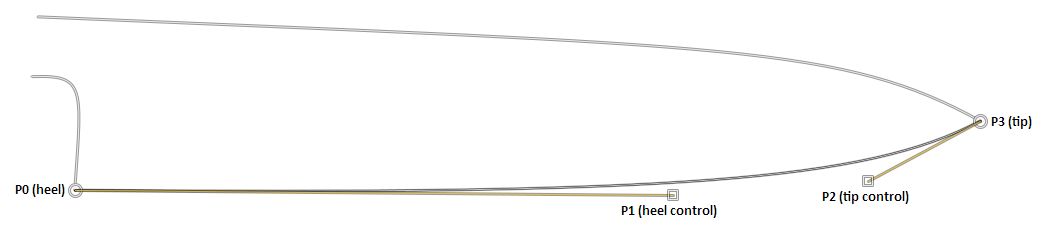
In this example, we're looking at the 3rd control point (P2). You can select the other control points to get their coordinates.

The other way to do it is to create the curve in a vector graphics editor, like Inkscape or Illustrator. You'll then export as SVG, and pop that open in Notepad (or your text editor of choice). Look for a line like this:

Code:
<path class="st0" d="M0,0c55.2,0,223,1.92,240-19.2"/>

Depending on the application, that could alternately look like this:

Code:
<path class="st0" d="M0,0 c55.2,0 223.2,1.92 240,-19.2"/>

In the above example, you can parse the following points:
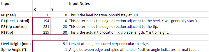
p0: (0,0)
p1: (55.2,0)
p2: (223,1.92)
p3: (240,-19.2)

Note that because SVG is oriented for web use, its Y-axis is inverted, so you'll want to negate the Y-values.

While you're in notepad, you can manually change those coordinates as desired and save - and it'll still open.

One real upside to the SVG approach is that it's in relative coordinates - so the location of p0 (the heel) doesn't matter as long as the flat spot is horizontal. That means that for a database, a user could simply upload an SVG with their trace of the edge, and everything else is handled simply in the backend. I will say that rotating things horizontal is much easier in CAD.
 
I'm a little lost on what the controls are. Are they just points which are on a tangent to the curve at the heel (or tip)? Or is the distance from the heel (or tip) to the control important? If so, how do you determine this when tracing a profile?
 
I'm a little lost on what the controls are. Are they just points which are on a tangent to the curve at the heel (or tip)? Or is the distance from the heel (or tip) to the control important? If so, how do you determine this when tracing a profile?

They're a bit... Loosey-goosey, perhaps?
They do determine the direction at the point they're associated with, but their length determines the amount of informed they have beyond that point. Think of them like elastic bands - you pull farther, and they pull harder.
Generally speaking, placing the control points further from their endpoints results in more gentle, longer curvature near that point. For example, putting both control points close to the endpoints will result in tight radii on each end, with a nearly straight line running between them (a nearly triangular blade shape). Extending the tip control point gives a more gentle curve at the tip, but a more pronounced belly. Extending the heel control point yields a longer flat. If you extend both, you end up with a sharper transition from flat to tip, more like a sakimaru takohiki or an American tanto. I'll post some examples a bit later.

As to placing them - I drag them around until it matches. I set them at the correct angle, then extend or shorten them until the curve matches.
 
I think I see. So it's a bit of trial and error moving the controls around until the profile matches your sample knife's profile?
 
To a certain extent, yes - but it only takes a couple minutes.

For example, a 240 gyuto seems to generally have a heel control 50-60mm directly horizontal from the heel, and a tip control a couple mm below the heel (at the appropriate angle).

Bezier curves, while funky mathematically, are fairly intuitive to create with some practice.
 
Bezier curves, while funky mathematically, are fairly intuitive to create with some practice.

I hope that didn't come off as arrogant, because I didn't mean it that way.

I think this GIF is illustrative of the actual role of the control points:

https://en.m.wikipedia.org/wiki/File:Bézier_3_big.gif


This actually makes me realize that placing P1 at Y=0 is often slightly incorrect - it would make the heel recurve bell-shaped if P2 is below 0. Therefore, P1 should actually point from P0 to P2. I think the easiest way is to put P1 on 0, then move it down once P2 is placed.
 
This actually makes me realize that placing P1 at Y=0 is often slightly incorrect - it would make the heel recurve bell-shaped if P2 is below 0. .
Can you give me an example of a bell-shaped recurve? I can't visualize what you mean by "P1 should actually point from P0 to P2. I think the easiest way is to put P1 on 0, then move it down once P2 is placed".

I had P2 below 0 in this earlier picture with no such recurve:
OXxYwPG.png
 
Last edited:
Can you give me an example of a bell-shaped recurve? I can't visualize what you mean by "P1 should actually point from P0 to P2. I think the easiest way is to put P1 on 0, then move it down once P2 is placed".

I had P2 below 0 in this earlier picture with no such recurve:
OXxYwPG.png
Hmm, yes, I suppose that was vague.
Take a look at my copy of the spreadsheet as it currently stands - at t=0 (also x=0), the control point forces the slope (dy/dx) to zero. Through t=0.06 (approx x=10mm), the slope becomes more negative - meaning the edge is concave there. If I hadn't used an absolute value in the curvature function, we'd have a negative curvature value, which indicates a curve being "concave down". I think that'll be useful to add.
From t=0.08 on, the negative slope levels off becoming fully flat around t=0.13, which means we've got a convex shape - as you'd expect a heel relief to be all the way to the very heel.

If, in contrast, you point the heel in the direction of the relief, you won't have any concavity. In the example in the spreadsheet now, I scaled the angle from P0 to P2 and put P1 along it. In particular:
Y(P1)=Y(P2)*X(P1)/X(P2)
In this example,
Y(P1)=(-2)*51.5/199=-0.51
Substituting that in for X at P1, I no longer have concavity at the heel.
I haven't yet done the overlay to see how much P2 will need to be corrected to compensate for overall shape changes.

All that said, it's quite miniscule. In the case currently shown, "heel relief" is only 30 microns.
 
Last edited:
I don't think it would be worth unlocking Y(P1) from zero as it would open up too many possibilities to throw the flat-spot off its reference plane. For example, what if we have a blade where P2 sits a few millimeters from P3? In this case, wouldn't your method (having P1 intersect the P0.P2 line) send P1 well into the positives? If this is the case, doing so opens up a can of worms when it comes to measuring any angles that were originally referenced off the flat-spot.

Also, I haven't found any gyuto profiles which require a negative Y(P2). In fact, today I borrowed some forum-popular knives off Marek07, and plan on taking some measurements to test out your spreadsheet over the next few days. I don't expect to find a knife that needs a negative Y(P2). but I'll let you know if I do.

And if all else fails, the 30 micron re-curve is easy enough to ignore. Consider that any particular run of knives will have far more than a 30 micron deviation throughout it's run to begin with, and many knives out there actually do have that damn re-curve at the flat. It's not done on purpose but it's there, and people ignore those re-curves all the time... much to my dismay! :mad:
 
Last edited:
I don't think it would be worth unlocking Y(P1) from zero as it would open up too many possibilities to throw the flat-spot off its reference plane. For example, what if we have a blade where P2 sits a few millimeters from P3? In this case, wouldn't your method (having P1 intersect the P0.P2 line) send P1 well into the positives? If this is the case, doing so opens up a can of worms when it comes to measuring any angles that were originally referenced off the flat-spot.
Yes, it certainly throws in some more variability, and may not be worth it - especially for 30 microns. What I meant, however, was only to move P1 down if P2 is below P0. Moving P1 above P0 isn't necessary. Here's an exaggerated example of that concavity:
upload_2018-10-12_10-37-41.png

Which won't be present if Y(P2) is positive (or P1 points to P2).

Also, I haven't found any gyuto profiles which require a negative Y(P2). In fact, today I borrowed some forum-popular knives off Marek07, and plan on taking some measurements to test out your spreadsheet over the next few days. I don't expect to find a knife that needs a negative Y(P2). but I'll let you know if I do.

That's really exciting, and I'm curious to hear more! I nabbed a photo of a Kato workhorse 240, and it seemed to require P2 of (199,-2) - but that was a very quick and dirty run with a 2° clockwise rotation, and I'm currently running the image straight, with P2 at (205,3.3).

And if all else fails, the 30 micron re-curve is easy enough to ignore. Consider that any particular run of knives will have far more than a 30 micron deviation throughout it's run to begin with, and many knives out there actually do have that damn re-curve at the flat. It's not done on purpose but it's there, and people ignore those re-curves all the time... much to my dismay! :mad:

Right, I think that's the ticket - I probably got overhyped before realizing the scale of the issue. I'm aware of the recurve on some knives - I thought I recalled in some cases it's intentional to help prevent heel sticking. I'd imagine it's more accurately represented as convex, which was my original point. It does complicate things unnecessarily, though. It's possibly worth considering for other knife types, but not really necessary on gyutos.
 
That's really exciting, and I'm curious to hear more! I nabbed a photo of a Kato workhorse 240, and it seemed to require P2 of (199,-2) - but that was a very quick and dirty run with a 2° clockwise rotation, and I'm currently running the image straight, with P2 at (205,3.3).

This is what I'm getting for the Kato workhorse after stealing a photo from Matus. :rolleyes:

It's amazing how much information we can get out of these three points.
I had to guess the scale of the picture, but the control points keep their relative positions if we change the ratio.
C7QOn6D.png
jff2LXg.png
 
Last edited:

Latest posts

Back
Top